
The PSD School
Section 15 by Lars Stenberg, ESDE AB
Unsuitable mechanical design solutions
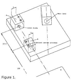
To conclude, we must investigate what happens if the optical components are installed in an inappropriate way. Figure 1 below shows how a laser diode, an achromatic lens and a main lens are mounted at the bottom of the prospective triangulation probe's housing with the aid of two holders A and B, manufactured of aluminium. According to chapter 6 of SiTek's 'PSD school' the distance a = 19.6 mm and H = 120 mm.
 Let us assume that the horizontal distance between the line of the tightened screws and
the system's optical axis c = 10 mm.
Let us assume that the horizontal distance between the line of the tightened screws and
the system's optical axis c = 10 mm.
Let us now assume that the triangulation probe is to be used to measure how much an engine casing is deformed when the engine becomes hot and, let us also assume that the collimated light beam from the achromatic lens strikes the engine casing perpendicularly and that the triangulation probe's temperature increases by 30ḞC in the course of the trial.
Firstly, we calculate how much 10 mm aluminium is expanded when the temperature increases by 30ḞC and the coefficient of linear expansion for aluminium is 23 ppm/ḞC. The result is 10?30?23.2?10-6 mm = 0.00696 mm. If, to start with, we assume that the holder B, and thereby the achromatic lens, does not move then this means that the laser diode will move to the left in Figure 1 in relation to holder B. This means that the system's new optical axis will form the angle 0.00696/19.6 radians = 0.000355 radians with the original optical axis. This, in its turn, means that the light spot on the engine casing, M, will move to the right in the Figure 1 section 0.000355?120 mm = 0.043 mm. Even if the distance between the triangulation probe and the engine casing is not altered during the trial the triangulation probe will nevertheless present a different distance due to the light spot being reproduced at another point on the PSD detector since the main lens registers a change of angle as soon as the light spot moves on the engine casing M.
In order to calculate the scale of the triangulation probe's error of measurement we must calculate the distance DH in figure 2 below. According to chapter 3 of SiTek's PSD school the angle a is 40Ḟ and H = 120 mm. With the symbols of Figure 2 we obtain with the aid of uniform triangles:
The calculation provides that DH=0.051 mm. We thus obtain a measurement error of 0.051 mm on account of the laser diode having moved to the left in figure 2,
 caused by the fact that there is 10 mm of aluminium material that is exposed to linear expansion
when the temperature has changed 30ḞC during the trial.
caused by the fact that there is 10 mm of aluminium material that is exposed to linear expansion
when the temperature has changed 30ḞC during the trial.
Please observe that we have not observed any mechanical movements or variations in the PSD detector or the triangulation probe's other electronics. If, for instance, the achromatic lens in the holder B moved as much to the right as the laser diode moved to the left the error would be doubled. If - on the other hand - the achromatic lens in the holder B were to move to the left as much as the laser diode we would obtain a much smaller error but with the opposite symbol since the laser spot would move to the left on the engine casing. Moreover, it is of interest to see how the main lens, which is placed at the distance AE = 120?tan40 mm to the right of the laser diode, is fixed in the triangu-lation probe's housing. Depending on how the main lens is mounted the resulting measurement error may vary between very substantial and significantly smaller measurement errors.
When an electro-optical instrument is exposed to heat changes, it has happened more than once that those who have carried out the test have the impression that a holder moves on account of poor fixing of the different components when - in reality - it is a question of linear expansion in the case of the materials incorporated in the instrument. For this reason an adhesive is applied between, in this case, the holder and the instrument housing. What may happen when the instrument is heated up again is that the adhesive softens at a certain temperature (for epoxy glue the temperature lies at >40ḞC) and the holder moves somewhat resulting in errors of measurement. When the temperature decreases the adhesive hardens again and - in the worst case - the holder is fixed in a new position. This may entail that the triangulation probe presents another measurement value than that which it did formerly at the same temperature. There are, thus, reasons to think carefully before using glue in mechanical constructions.
As for myself, I normally record how an instrument measures in the course of heating or cooling under controlled test conditions in order to find out if the instrument in question measures differently at different temperatures. In this case the controlled test conditions would mean that the triangulation probe is placed in a box in which the temperature may be varied. The collimated light beams must then pass perpendicularly through a parallel plane window of good optical quality and the reflected light must likewise pass perpendicularly through a parallel plane window of good optical quality.
This means, therefore, that both the windows form an angle with each other. In addition, one must carefully think through how the triangulation probe, which is to be tested, must be fixed inside the test box so that the placement in the test box does not in itself introduce errors in the distance measurement when the temperature is changed.
If one removes the measured distances as a function of temperature and a bump on the curve at approx. 42ḞC is formed one knows then that epoxy glue is very probably at least part of the explanation for the measurement value drift when the temperature is changed.
In this case it is not a question of adding more adhesive but instead removing adhesive when the triangulation probe is mounted. Instead of gluing a component fast it may be necessary to use a screw-in mount for example.
As the reader no doubt realises, there is a great difference between constructing a measuring instrument that is to measure with almost the same precision over a large temperature range and constructing a measuring instrument for room temperatures. However, even if the constructor responsible is aware of the problem it may very well happen that the customers attempt to use a measuring instrument for a measurement application that the instrument is not designed for. For this reason customer-related problems are frequently avoided if one clearly declares within which temperature range the instrument in question is intended to be used.
Conclusion
This is the 15th and last chapter on the optical and mechanical construction of a triangulation probe. Naturally, the scope of the articles could have been extended considerably but I hope, nevertheless, that the different approaches to the problem that I have adopted may be of benefit while being of general interest for all those who work with electro-optical instruments.
|
ḋ home