The PSD School
Section 5 by Lars Stenberg, ESDE AB
How to select the condenser optics for a tringulation probe
In section 2 of Sitek's PSD school, we looked at the design parameters for a triangulation probe and derived the 11 formulae which can be used to design the geometry of a triangulation probe. In section 3, these formulae were used to make a closer study of how the geometry of such a probe is designed, and also calculated the aperture of the main lens. In section 4, we went through selecting the light source and generating a so-called quasi-collimated light beam. The aperture of the condenser lenses was calculated in section 4. In this section and in subsequent sections, we will discuss how to calculate and select suitable optical components for making a triangulation probe.
What type of light source should I select?
The calculations in section 4 directly affect the choice of light source. In these calculations, the Gaussian1 magnification is 4 times in our example. If the light source has a maximum geometric extent of 1 mm,
 the illuminated image of the light source
on the measurement object will have a dimension of 4 mm. In practice, this eliminates all
kinds of bulbs. What remains to choose from are light emitting diodes and laser diodes.
the illuminated image of the light source
on the measurement object will have a dimension of 4 mm. In practice, this eliminates all
kinds of bulbs. What remains to choose from are light emitting diodes and laser diodes.Light emitting diodes generally have a larger light emitting area than laser diodes and are also frequently provided with a cast epoxy lens whose purpose is to focus the light. It is frequently necessary to dimension a LED in this way because the light which leaves the emitting surface is spread over a hemisphere. Unfortunately, the cast epoxy lens has poor optical properties, with all the known optical aberrations2, which makes it very difficult to add further lenses to get a well focused, sharp, point of light. If we select a LED without an epoxy lens, we can only make use of the light which passes through our condenser lens. This means that if we select a LED whose light emitting surface is 0.3 x 0.3 mm, the image will be 1.2 x 1.2 mm, and the generated light spot will also be quite weak. A spot of light, of dimensions 1.2 x 1.2 mm, is not sufficiently one-pointed if you want to measure the threads on an M6 screw, for example.
We are forced slowly but surely in the direction of a laser diode, which is unfortunately both more expensive and more complicated to make the electrical connections to, than a LED or light bulb. But the big advantage of the laser diode is that it is a more or less perfect point source of light, from an opening which frequently has dimensions of about 5 x 1 mm. This means that with 4 times Gaussian or geometric magnification, the dimensions of the light spot will be 20 x 4 mm. Since we are now beginning to use dimensions which approach the wavelength of light, we must check to see how the diffraction of light affects the dimensions of the light spot.
Because of the wavelength of light is not zero, the light waves emanating from different parts of an object will sometimes reinforce each other and sometimes cancel each other out. This means that a there is lower limit to the size of objects which can be studied in detail when light of a certain wavelength is used. The formula which specifies the limit of resolution when you use imaging lenses in a circular mount is:
sin Q = 1.22 l/A
where Q is the angular resolution in degrees, l is the wavelength in mm and A is the aperture or diameter of the imaging lenses in mm. If we calculate the resolution of the human eye at a wavelength of 555 nm (maximum intensity of solar radiation), when the diameter of the pupil is 2.4 mm, we get
Q = arcsin (1.22 x 555 x 10-6/2.4) = 0.016
Since 0.016 is expressed in degrees, we get the angular resolution of the eye in seconds of arc if we multiply 0.016 by 3600, which gives 58.19 seconds, or 0.97 minutes of arc. This is why the angular resolution of a healthy eye is normally specified as being 1 minute of arc. The above formula shows that you can see smaller objects if you either choose light of a shorter wavelength or use imaging lenses of greater aperture.
It can be derived3 from the definition of resolution, that the image diameter, measured in mm, D, when a point source of light is imaged, is4
D = s x (2.44 x l/A)
in which s is the distance from the imaging lenses to the image in mm, l is the wavelength in mm and A is the aperture, or diameter of the imaging lenses in mm. Note that D will be small if s and l are small and/or A is large.
We know that s in our example is about 120 mm and there are laser diodes which lase at a frequency which provides red light at a wavelength of 635 nm. Let us calculate D when A = 2.5 mm. Put into the formula above, this gives D = 0.074 mm. Note that even if the actual light source really is a point, the image will still be 0.074 mm in diameter since the wavelength of light is not zero. (On the other hand, the image can be much larger if the condenser lenses which form the light image are not sufficiently well corrected, but this is a problem which has to be solved by adjusting the geometry of the lenses).
Because of the geometric or Gaussian magnification, in combination with the diffraction effect, the dimensions of the light spot become (0.02 + 0.074) x (0.004 x 0.074) mm = 0.094 x 0.078 mm.
If we do the corresponding calculation for A = 1 mm, we get D = 0.186 mm. In other words, we get a smaller spot of light by choosing a larger aperture for the imaging condenser lenses.
What aperture should the condenser lenses have?
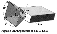
Should we select 2.5 mm? Before I answer that question, we are going to study the beam which leaves the laser diode more closely. The data sheets for various laser diodes which lase at 635 nm specify that the portion of the beam which is at right angles to the lengthways direction of the emitting surface
 (app. 5 x 1 mm) is spread through an angle
of 35° whereas the portion of the beam which is parallel to the lengthways direction of
the emitting surface is only spread through about 7°. Please refer to illustration 2
below. This is caused by the fact that the dimensions of the emitting surface begin to
approach those of one wavelength of light, and this is thus a diffraction effect. (The
reader can use the formula to check the calculations for resolution shown above, but since
we are now using a slit-shaped opening, the constant of 1.22 in the formula, which applies
to circular openings, should be replaced by a constant of 1.00, i.e. the formula should be
reduced to the wavelength divided by the opening).
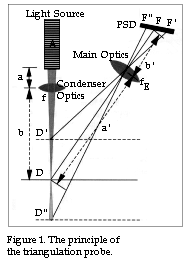
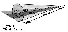
In order to make use of as much light as possible from the laser diode and obtain a circular beam at the same time, we should select an aperture for the condenser lenses which makes the light from the laser diode fill the entire aperture of the condenser lenses. Since the beam angle was 7° at its narrowest, this gives half the aperture ak, for the condenser lens, using the designations in figure 3, as tan 3.5 = ak/30, i.e. ak = 1.83 mm. (In section 4, the distance from the light source to the condenser lens, designated as a in figure 1 and in figure 3, section 4, was calculated to be 30 mm).
But this means that we get a circular beam of diameter 3.76 mm, which admittedly means that the diffraction will be 1.5 times less than we had recently calculated, but the beam from the condenser lens will be as depicted in figure 4, which means that the diameter of the light spot will vary unnecessarily throughout the measurement range of the triangulation probe.
 If we want a beam of 2.5 mm diameter, the distance a in figure 1 should be 1.5
times smaller, i.e. about 20 mm.This means that if we put in a = 20 and b = 120 in the
lens formula, the aperture of the condenser lens becomes 17.1 mm instead.
What optical properties should a suitable condenser lens of aperture 17.1 mm have?
Well, that is a question I will attempt to answer in sections 6 and 7, and we will also investigate the difference in optical quality between an optical system which consists of a single lens and an optical system which contains several lenses. We will also analyze various optical systems which can be purchased ready made and discuss the question of ordering a special design.
|
« home